 Spovex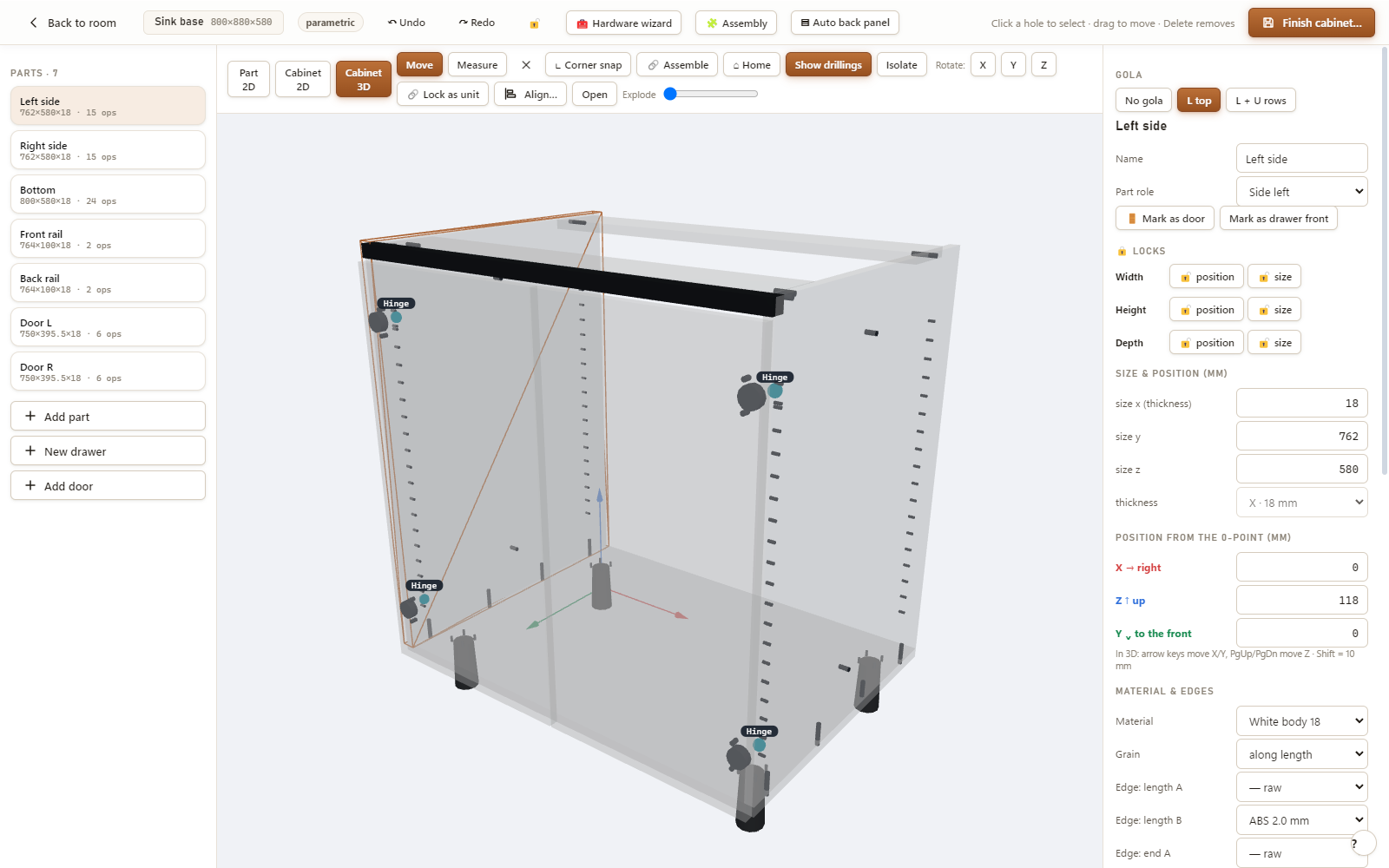
A kitchen can look complete on screen and still be far from ready for production. The visual scene may show every base unit, tall cabinet and worktop in the right place, yet the factory still needs exact panel dimensions, material and edging assignments, hardware decisions, drillings, cutlists, labels and machine instructions. Every time those facts are copied into another program, a person must interpret them again. That handoff is where swapped dimensions, old revisions and missing operations can enter the job.
This is why manufacturers search for kitchen cabinet design software with CNC export. The useful goal is not merely a button that produces a file with a familiar extension. It is a dependable chain of project data: room constraints shape cabinet choices; cabinet rules create parts; hardware choices create machining; parts feed material lists and optimization; and the approved production data is translated for a specific machine environment.
The route from design intent to a cuttable job
- Capture the room and design the kitchen.
- Build with cabinet rules instead of disconnected lines.
- Resolve hardware through task-focused wizard pages.
- Inspect exceptional parts and their drillings.
- Generate BOMs, cutlists and labels from the same revision.
- Optimize panels with shop rules.
- Translate approved data through the correct machine driver or post.
- Validate, test and only then release production.
1. Start with the real room, not an isolated cabinet
The first useful model is the room. Record the geometry that controls the design: wall lengths, ceiling height, openings, corners and the positions of fixed services or appliances. A photorealistic view can help a client understand the proposal, but production begins with constraints. A beautiful cabinet placed across a door swing or in conflict with an appliance is still a design error.
Within one project, room data gives the cabinet run a shared coordinate system. Designers can arrange units, fronts and worktops while keeping the relationship between neighbouring cabinets visible. Changes are easier to reason about because they happen in context. If a tall unit widens, the remaining run changes; if an appliance moves, adjacent fillers and cabinets may need review. The goal is not automatic design without judgement. The goal is to make the consequences of a decision visible while the job is still cheap to change.
Spovex combines room and cabinet design with photo rendering through Cycles, so presentation and production start from the same project rather than separate copies. Rendering answers a client-facing question—“Is this the kitchen we want?”—while the cabinet model carries manufacturing facts. Approval of the appearance should still be treated separately from approval of technical details.
2. Let cabinet rules carry the revision
A production cabinet is more than six rectangles. Its parts depend on construction decisions: overall width and height, material thickness, joint logic, shelves, fronts, back construction, plinth or leg arrangement and the clearances required by hardware. Parametric cabinet rules keep those relationships together. When an authorised dimension changes, the affected parts can recalculate from the cabinet definition instead of relying on a designer to find and redraw every panel.
This matters most during revision. Imagine that the client approves a wider drawer bank after the first design. In a disconnected workflow, the visual cabinet, side panels, drawer hardware, cutlist and CNC drawings can each become a different version. In a connected workflow, the project change becomes the source for the downstream result. The operator still reviews the output, but the software does not require the same dimension to be typed repeatedly.
Rules reduce repetition; they do not replace shop standards
Every shop has construction methods that must be represented deliberately. Materials, thicknesses, clearances and joints should match what the business actually builds. A default is not evidence that a choice is correct. Before using a cabinet family on live work, manufacture a controlled sample, check the assembled dimensions and preserve the approved rule set as the shop’s baseline.
3. Turn hardware choices into machining decisions
Hinges, runners, lift systems, handles and other fittings are not decorations added after the cabinet is drawn. They affect counts, clearances and drilling. A hardware wizard is valuable when it presents the decision as a clear task—choose the required system for this door or drawer—and then carries the associated data to the relevant parts.
Spovex uses task-focused hardware wizard pages so the designer can work through fittings in the context of the cabinet. The important connection is not the brand name on a list. It is that the selected article and configuration can inform the required placement and operations, while the project retains which choice produced them. If a hardware selection changes, the drilling result must be reviewed again; an old machining file should never be assumed valid after a fitting revision.
Good workflow also makes unresolved decisions visible. If a cabinet has not yet received its final hinge or runner system, the team should know that before release. Manufacturing documents are most trustworthy when “not decided” cannot quietly masquerade as “approved.”
4. Inspect the part, the face and every drilling
Cabinet rules cover repeatable construction, but real projects include exceptions: a service opening, a shaped end, a special groove, a pocket or a drilling pattern that needs close inspection. The part editor is where the manufacturing object becomes explicit. Dimensions, faces and operations should be understandable without returning to a separate sketch that can drift away from the job.
Drillings deserve more than a quick visual glance. Confirm the reference face, offsets, diameter, depth and whether an operation is blind or through. Check that front and back operations have not been mirrored by an orientation assumption. For grooves and routed shapes, review tool access, depth and corner conditions. These are manufacturing checks, not merely drawing checks.
Make the exceptional part traceable
When a designer edits a single part, the reason should be clear to the next person. A production operator should be able to connect the part shown on the label with the part in the project and the program prepared for it. That traceability is more useful than a folder full of filenames whose relationship to the approved kitchen is known only by one employee.
5. Generate BOMs, cutlists and labels from one approved revision
Once cabinet and hardware decisions are resolved, the same project can provide the bill of materials, panel cutlist and labels. This is the point where a connected workflow pays back the discipline used earlier. Material, thickness, dimensions, quantity and edging should come from the parts that were actually approved, not from a manually retyped summary.
A bill of materials supports purchasing and job preparation. The cutlist organizes what must be produced. Labels identify each physical panel after cutting, when many rectangles can otherwise look alike. A useful label links the panel back to the project and part identity and can carry the information the shop needs at the next station. The exact label content and barcode workflow must match the shop’s process and equipment.
Revision control is essential here. If the design changes after documents have been issued, regenerate the affected outputs and withdraw the obsolete set. Printing a fresh list without removing the previous one can leave two apparently valid instructions on the shop floor. “Generated by software” does not solve that process problem; a clear release rule does.
6. Optimize panels with the rules that exist at your saw
Cutting optimization arranges required parts on available boards. Its result depends on real inputs such as board size, trim, saw kerf, permitted rotation and grain direction. A small mistake in those rules can make a neat diagram unusable. The operator should know which values came from the material specification, which came from the machine and which are shop policy.
In Spovex Pro, the cutting optimizer remains within the project flow, so the panel set does not need to be recreated before nesting. Review the proposed patterns for material identity, grain, part quantities and practical cutting order. Optimization is a decision aid, not permission to ignore handling limits or the saw manufacturer’s instructions.
Material yield matters, but the lowest theoretical waste is not always the safest or fastest plan. Very small remnants may not be useful, awkward sequences may slow production, and grain-sensitive fronts can constrain rotation. For a deeper look at those trade-offs, read How Panel Cutting Optimization Saves Material.
7. Use a machine driver built for the actual environment
The final software handoff is post-processing: translating approved project operations into the syntax, orientation and conventions expected by a machine or its companion software. This is where vague claims such as “CNC compatible” are dangerous. Two machines may perform similar work and still require different file formats, controller settings, coordinate systems or tool mappings.
Spovex Pro supports machine-driver workflows for Biesse-, Selco- and Homag-class environments. “Class” describes supported workflow families; it is not a promise of universal compatibility with every model, controller revision or custom machine configuration sold under those names. Before purchase or rollout, provide the exact machine model, controller, software version and required output path so the intended workflow can be confirmed.
A post is a translation, not a substitute for configuration
The project may know that a panel needs holes and a groove, but the machine environment determines how those operations are expressed and executed. Tool identifiers, usable diameters, drilling-head layout, origin, face convention, safe motion and clamp zones all affect the result. Some checks belong in software; others belong to the machine operator and the manufacturer’s documented procedure. The safe approach is to treat the post, machine configuration and shop procedure as one controlled setup.
8. Validate before the first production panel
A connected data flow removes avoidable re-entry, but it cannot prove that the physical world matches every assumption. Validation should happen at several levels. First, review the kitchen: room fit, appliance clearances, cabinet dimensions, opening directions and the client-approved design. Second, review production data: materials, thicknesses, edging, quantities, hardware and operations. Third, review machine translation: part orientation, faces, origin, units, tool mapping, program naming and the route by which the file reaches the controller.
The test should be simple enough to inspect and representative enough to exercise the intended output. Do not begin with a costly client panel. Measure the physical result with appropriate instruments. Confirm hole positions and depths, through operations, grooves, edges and the relationship between the label and program. If the controller, tool table, post or machine configuration changes later, repeat the relevant qualification rather than relying on a test from an older setup.
A practical release checklist
- The design revision is approved and obsolete documents are withdrawn.
- Room constraints, appliance details and opening clearances have been checked.
- Every cabinet uses the intended construction rules, materials and thicknesses.
- Hardware decisions are final, and associated drillings have been inspected.
- Part faces, offsets, diameters, depths, grooves and exceptional shapes are correct.
- BOM quantities, cutlists, optimization inputs and labels match the released revision.
- The exact machine model, controller, software version and post are confirmed.
- Tool mapping, origins, orientation, units and transfer method are verified.
- An authorised operator has completed and measured a safe test cut.
What changes when the project stays connected?
The strongest benefit is not a dramatic “one click” moment. It is continuity. The designer and production team can discuss the same cabinet, part and revision. A hardware choice can lead to the drilling that must be checked. The panels sent to optimization come from the released design. A label can identify the physical result. The machine output can be traced back to the part that created it.
This continuity reduces places where people must copy and reinterpret data, while preserving the points where professional judgement is required. Designers still resolve the room. Engineers still approve construction and machining. Operators still own safe machine setup and physical verification. Software supports those roles best when it makes their shared facts visible instead of pretending the last export button makes every decision automatically.
If this is the workflow your shop needs, explore the full Spovex design and manufacturing modules, compare what is included on the pricing page, or book a live demo. Spovex Pro is the tier for cutting optimization and machine-driver workflows; exact machine and controller fit should be confirmed for your environment.